The Miniature, Rugged Alternative to LVDTs and Linear Potentiometers
|
|
The Miniature, Rugged Alternative to LVDTs and Linear Potentiometers
|
Order • About • Site Map |
|
|||||||||
Application Note for Draw Wire Transducer Accuracy |
Table of Contents
OverviewSpaceAge Control draw wire transducers [string potentiometers ("string pots") and string encoders], like all sensing devices, deliver sensed data containing errors. For the broad majority of applications, the magnitude of these errors is acceptable. This document will review the design features that lead to error, describe the errors, and then demonstrate how SpaceAge Control transducers reduce the error magnitude. In addition, tips are provided for users to compensating for or reduce error. For those readers only caring about "the bottom line" or pressed for time, review the Error Contribution Summary section Draw Wire TransducersDraw wire transducers are used to convert mechanically-measured data into an electrical signal that can be used as input to data acquisition or control systems in a broad array of applications. The chassis of a draw wire transducer is generally static-mounted while the draw wire is attached to a moveable object. As the object moves, a rotary sensor in the transducer chassis produces an electrical signal that represents the distance the object has moved.
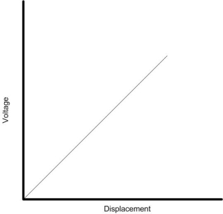
Figure 1 - A Conceptual Draw Wire Transducer Like all sensing devices, draw wire transducers are subject to various types of error. Before exploring the different ways that transducer accuracy can be affected, it is important to exactly define error, accuracy and precision. ErrorError is defined as the difference between the true value of the quantity being measured and the result of the measurement. An analysis of the collected error data can determine if a draw wire transducer experiences error because of poor accuracy, poor precision, or a combination of both. Accuracy Versus PrecisionAccuracy is defined as the extent to which the values indicated by the measurement system conform to the actual values, whereas precision is defined as the consistency of the measurements to show the same or similar values. Figures 2-5 and the accompanying text explain these two characteristics. An ideal position/voltage output plot should produce a linear slope. Figure 2 gives an example of an ideal plot with output as a function of position.
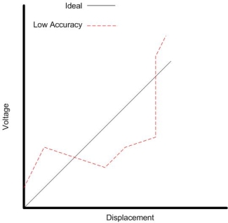
Figure 2 - Ideal Voltage/Output Plot A draw wire transducer with low accuracy produces outputs of wide variations from the ideal plot. Figure 3 shows an example of this.
Figure 3 - Low Accuracy Example A draw wire transducer with high accuracy produces outputs with small variations from the ideal plot. The quantity of variations is not as much of a concern as the quality of the outputs. Since the output quality is high in this example (the outputs do not deviate much from the ideal plot), the accuracy of this transducer is high. Figure 4 shows an example of this.
Figure 4 - High Accuracy/Low Precision Example A draw wire transducer can give the user a high-accuracy reading while being imprecise. Precision is defined as the consistency of an outcome when a sample is repeatedly taken. Data collected with high precision but low accuracy produces the same output every time - even though a consistent difference exists between the readings and the ideal plot. Figure 5 shows an example of a high-precision/low-accuracy draw wire transducer.
Figure 5 - High Precision/Low Accuracy Example An example of a low-precision transducer can be seen in the previous example illustrated in Figure 4. Because there are many variations along the output plot, the level of precision is low even though the outputs are close to the ideal mark. String Encoders Versus String PotsDraw wire transducers can use encoders ("string encoders") or potentiometers ("string pots") as the sensing component. Encoder-based draw wire transducers are less prone to certain types of error typical to potentiometer-based draw wire transducers such as noise and hysteresis. However, an encoder-based transducer may have lower resolution (discrimination) than a potentiometer-based draw wire transducer. This document focuses on string pots although much of the material is applicable to string encoders also. CalibrationBefore any draw wire transducer is used, confirm the device has been properly calibrated. If calibration has been performed improperly, any data measured with the transducer will be invalid. One indicator of poor calibration is if the transducer shows high precision but low accuracy, as seen in Figure 5. The transducer in this example shows that its sensor is consistently producing the same measured output as a function of position. However, the output is off by a set value. Recalibrating the draw wire transducer to compensate for this static offset will eliminate a major source of error and improve its overall accuracy. SpaceAge Control draw wire transducers are calibrated upon customer request before shipping. Transducers are actuated and 11 data points of draw wire displacement and draw wire tension are collected. The results are reported on the Acceptance Test Data Sheet. The calibration procedure abides by the standards set forth by the Variable Electronics Components Institute's industry standard for precision potentiometers. Repeatable ErrorsNon-LinearityAn ideal draw wire transducer should produce a completely straight output vs. position plot as seen in Figure 2. In the real world, transducer plots are never a straight line. This can be caused by natural wear in the spool, producing slightly irregular offsets in data points. Other causes include permanent deformation of some parts of the cable due to constant high levels of tension and any slight mechanical offset created through component thermal expansion. Non-linearity is defined as the maximum difference between the ideal transducer (straight or linear plot) and the real transducer (curved or non-linear plot). Non-linearity is generally the biggest contributor to error for draw wire transducers. Figure 6 shows an example of an ideal transducer and a real transducer on the same plot.
Figure 6 - Ideal and Real Transducer Plots Unlike an ideal transducer plot, it is not necessary for a best straight-line (BSL) plot to go through a certain plot point. Instead, the BSL is a straight line drawn through the real plot that comes closest to matching all of the output data points. The non-linearity error is again defined by calculating the maximum difference between the BSL and the real transducer plot. Transducer data can be calibrated to minimize error impact by adjusting readings to compensate for the non-linearity error. SpaceAge Control provides an online calculator (./calclin.htm) for users to calculate non-linearity error. The calculator requires 11 real data points and the transducer's maximum range to produce the error value. Thermal: MechanicalDraw wire transducers, as with any mechanical device, are subject to mechanical errors caused by temperature such as thermal expansion. The amount of variation due to thermal expansion depends on the thermal properties of the transducer's materials. Thermal expansion can affect many different components of the transducer:
Mechanical errors caused by thermal conditions can be difficult to identify. Careful analysis, combined with the use of temperature sensors, can usually allow users to determine the source of the thermal error. For SpaceAge Control transducers with known material properties, the error due to wire thermal expansion as a percentage of the transducer's full scale can be calculated if the following values are known:
The equation for change in cable length (DL) is: DL = A * L * DT Thermal error can often be disregarded due to its minor effect. The effect is particularly immaterial if the item being monitored has the same coefficient of thermal expansion as the draw wire transducer. Thermal: ElectricalExtreme thermal conditions can also affect the electrical components within a draw wire transducer. However, because SpaceAge Control transducers are used as voltage dividers (using voltage variance) instead of rheostats (using resistance variance), any changes in resistance occur uniformly throughout the resistive material. This uniform change prevents any voltage change due to temperature effects, protecting SpaceAge Control transducers from electrical error caused by temperature change. Displacement Cable SagIdeal displacement of a cable from a draw wire transducer has the cable stretched in a completely straight line. However, cable sag can result due to gravity, air flow, and other forces that may load the cable perpendicular to its length. The tension on the wire is just one of the built-in methods designed to prevent a significant amount of cable sag error. When cables are exceptionally long (over 60 feet) and displaced at an angle non-parallel to the force direction, the potential for cable sag increases and errors change from negligible to noticeable. Cable sag is generally not an issue when the transducer is used in zero-gravity environments or when the cable is displaced in the same direction as acted on by gravity or similar forces. Figure 7 illustrates an exaggerated depiction of cable sag.
Figure 7 - Displacement Cable Sag Cable sag is a repeatable error and can be calculated if the following values are known:
The equation for calculating cable sag (S) is: S = (E/4) * Square Root (6 * (L / E - 1)) In order to use this equation, the cable length (L) must be calculated using the following equation: L = 2 * (sinh (E / (2 * (F / (W*G)))) SpaceAge Control provides an online calculator (./calccabl.htm) for users to easily determine the generally-insignificant cable sag error involved with using a draw wire transducer. Displacement Cable StretchAny cable subject to a high-tension force is susceptible to stretching due to the elastic properties of the cable material. If the applied tension is greater than the material's yield point, some degree of cable stretching will occur. Cable stretch can be approximated if the material properties, cable details, and applied load are known. However, cable stretch occurs on a case-by-case basis, and it is difficult to exactly determine the amount of error involved. Fortunately, the amount of error is nearly always small enough that it can be considered negligible. SpaceAge Control provides an online calculator (./calcstre.htm) for users to approximate the amount of cable error. The calculator assumes the cable is constructed of specific stranded stainless steel wire rope and requires the following values:
HysteresisIn general terms, hysteresis is the permanent deformation that a system experiences when a force is applied to it. Hysteresis error is defined as the level of this deformation and its ensuing offset value to data collected from the system. In terms of draw wire transducers, hysteresis error refers to the offset calculated by approaching a set of data points from opposite directions. To calculate hysteresis error, measurements should be taken at a pre-defined set of points. In the following example, we will use positions A, B, C, and D. Measurements should first be taken in the order of A, B, C, and D. After those measurements, direction should be reversed and measurements should be taken in the order of D, C, B, and A. The error can be calculated by comparing the measurements at each point. This process can be repeated for statistical validity. Taking an average of the differences can give an average of the hysteresis error. Users can minimize the impact of hysteresis error by adjusting the transducer data to compensate for the calculated average difference. The primary causes of hysteresis errors in potentiometer-based draw wire transducers is potentiometric wiper shifting and cable tension hysteresis resulting in cable stretch change. Sine ErrorSpaceAge Control transducers use a threaded drum to help minimize error from cable wrap. This type of drum is susceptible to sine error, a small contributor to overall error. An ideal drum has a perfectly linear set of output data points. However, with a threaded drum, sine error can produce data points that are offset slightly and follow a sine wave pattern along the ideal linear line. Non-threaded drums produce a similar sine error but such error is not repeatable, as the cable is not guaranteed to fall into any one position on the drum. Non-Repeatable ErrorsRepeatabilityRepeatability error is the variation in the data collected from a draw wire transducer. Repeatability error is calculated by collecting data at the same point over and over, then comparing the data to see the differences in each measurement. This measurement can be taken as many times as necessary to provide statistical validity. Repeatability error (E) can be calculated if the following values are known:
The repeatability error (E) is a percentage that can be determined by the following equation: E = (M - A) / A DriftDrift error in a draw wire transducer refers to the cumulative errors that appear in data measurement when environmental conditions and the quantity being measured remain the same. When calculating drift error, time is the only variable involved. Tests to determine drift error require the following conditions:
Short-term drift is defined as the drift that occurs during a period of 24 hours or less. Long-term drift is defined as the drift that occurs during a period of one month or greater. Many different factors can affect both short-term and long-term drift, such as mechanical instability, noise, mechanical damping, and mechanical wear. Because of all of these different factors, it is difficult to generate repeatable errors and careful analysis is required to identify the source of the problem. Drift error is generally immaterial in draw wire transducers. NoiseNoise is a generic term that encompasses a variety of conditions produced by the power supply that affect the electrical output signal. Noise problem in potentiometric draw wire transducers can be attributed to a number of different causes including:
Because of the random nature of noise, this type of error is non-repeatable and generally not correctable. Noise can, however, be reduced by a variety of methods found using a Web search engine. ResolutionNo measuring device will ever be absolutely perfect. Any measured data is only as good as its resolution. Because sensing devices are not infinitely adjustable, they do have a finite step that can be sensed. This finite step is called resolution and measurement increments smaller than the sensor's resolution will result in an error -- even though this error may be insignificant for your purposes. The last significant digit of each measured value is rounded. Depending on the type of data collection you are using the transducer for, this small bit of rounding may stagger on to subsequent data for cumulative measures. SpaceAge Control draw wire transducers use high-resolution sensors to minimize the impact of this type of error. This type of error cannot be eliminated. SpaceAge Control Design Features That Reduce ErrorSpaceAge Control draw wire transducers are designed with the understanding of what repeatable factors contribute to error. Certain features unique to SpaceAge Control transducers are implemented to specifically minimize certain types of error. Threaded DrumWhen a cable recoils and begins to wrap itself back on to a drum, a potential for error exists in the way the cable wraps. If the cable wraps upon itself, the rotary sensor may be off and a constant gap variability may occur from cycle to cycle leading to inconsistent results for cable displacement. SpaceAge Control transducers all use drums with grooves or threads to ensure that cable winding consistently occurs without any overlapping wrap upon itself. This feature allows for increased accuracy and repeatability of the transducer's measurements. For example, let's use the situation of the displacement cable wrapping over itself on a non-threaded drum for just one revolution. Using a 2-inch (50.8 mm) diameter drum and a 0.027-inch (0.6858 mm) diameter displacement cable, the threaded drum will provide an output of 6.326-inch (160.67 mm). If a non-threaded drum is used and the cable wraps up on itself for only one revolution, the circumference on that revolution will be 6.368-inch (161.747 mm). This cable overlap adds a repeatability error of ±0.335% for the non-threaded drum solution. Direct Drum/Sensor ConnectionThe way a drum is connected to the sensor shaft affects both overall durability and accuracy. Some manufacturers elect to use a spring connection between the drum and the sensor shaft. This design does have some merits; the use of a spring prevents damage to the sensor internal stops. However, having a spring connector means that whenever shock and vibration enter the system, there is little consistency in the sensor results. This lowers the transducer's repeatability. Even though the spring may add modest lifespan to the transducer's components, the potential accuracy issues that come with low repeatability nullify this benefit for many applications. A transducer that has low repeatability may be an inferior design choice. SpaceAge Control's transducers use a unique design that pins the drum directly to the sensor shaft. This eliminates any potential errors caused by the effects of vibration and shock to a spring-loaded system. Precision ManufacturingSpaceAge Control uses precision-machined/molded components with tight tolerances (±0.001 to ±0.005 inch (±0.0254 to ±0.127 mm)). This attention to manufacturing detail means that SpaceAge Control draw wire transducers stay within data sheet limits and, additionally, help to minimize error from mechanical sources. Pre-Stretched WireSpaceAge Control pre-stretches wire to reduce the potential error caused by wire stretch. By pre-stretching the wire, much of the wire's inherent "give" can be assimilated into its natural length. Once the wire is pre-stretched, the draw wire transducer is less susceptible to error from further wire stretch. Low-Mass WireSpaceAge Control uses a low-mass wire for its draw wire transducers. Because the relatively lightweight wire is less susceptible than other heavier wires to cable sag, any errors associated with displacement cable sag are minimized with this material selection. Premium-Quality Rotary SensorsRotary sensors of higher quality stand out among their competition by having fewer complications from issues such as noise and hysteresis while generally providing a high level of repeatability. SpaceAge Control uses only the best rotary sensors available on the market as components for draw wire transducers to minimize any potential errors produced by the sensing mechanism. Error Contribution SummaryAn error may be repeatable (systematic error or bias) or non-repeatable (random error) depending on its source. Repeatable errors appear consistently and can often be rectified through calibration and data augmentation. Non-repeatable errors are often inherent within the device. Due to their sporadic nature, it is difficult to compensate for non-repeatable error. Table 1 lists different types of error and their typical values for SpaceAge Control draw wire transducers. Draw wire transducers are subject to both electrical and mechanical errors. Everything from the transducer material's thermal coefficients to sensor component manufacturing toleranes can create error. Analyzing the environment the transducer is used in can usually define what potential sources of error may be and how calibration and adjustments can be used to minimize the error.
Table 1 - Error Sources and Typical Values of SpaceAge Control Draw Wire Transducers Conclusion? SpaceAge Control draw wire transducers have total error that is acceptable for the broad majority of applications. For those applications requiring lower error magnitudes, alternatives such as laser and linear and angular scales may be considered. Bibliography
Additional Resources |
||||||||||||||||||||||||||||||||||||||||